logo
  • +91 7709 006491

  • info@cabinetindia.com

  • Survey no.27/2/2,

  • Pune, Maharashtra, India

  • 08:00 - 16:30

  • Monday to Saturday

STEEL

  • CTL (CUT TO LENGTH)
  • SLITTER
    • image
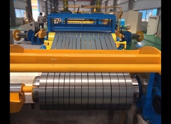
      • A Slitting Line is used to break master coils down into smaller coils of a specific width and or weight. A Slitting Line will uncoil a master coil and slit it to a specified width(s). The slit coils sometimes referred to as “mults” or “strips” are then recoiled. The finished slit coils produced by Slitting Lines are used in a wide variety of applications such as roll forming, stamping operations, and tube production.
      • The whole line is controlled by PLC with SCADA or HMI.
      • This line can help to improve efficiency, lower cost and ensure quality.
      • This line is applicable for processing of copper, aluminum, cold-reduced material, hot rolled material, silicon steel, and stainless steel and so on.
  • SKIN PASS MILL
    • image
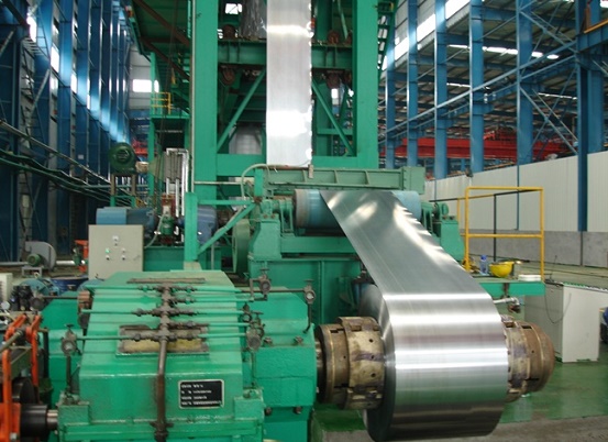
      • The device uses skin pass rolling to improve the mechanical properties and surface texture, and improve flatness, in order to form materials such as hot-rolled steel sheets, cold-rolled steel sheets, stainless steel plates, and aluminum plates into final products.
      • The advantages of skin-pass mills (also known as temper mills) include tight strip elongation tolerances; excellent flatness performance; high surface quality with respect to roughness, peak count and low residuals; and the availability of wet and dry skin-passing modes.
  • AGC (AUTOMATIC GUAGE CONTROLLER)
      • Automatic rolling process is a high-speed system which always requires high-speed control and communication capabilities. Meanwhile, it is also a typical complex electromechanical system; distributed control has become the mainstream of computer control system for rolling mill. Generally, the control system adopts the 2-level control structure—basic automation (Level 1) and process control (Level 2)—to achieve the automatic gauge control.
      • The basic automation Level 1 accomplishes the fast collection of process information and the output of control results; controllers in this level are high-speed embedded controllers or high-performance PLC. Because of the time requirement of fast loop control, network communication rates among controllers are also highly demanded.
      • Composed of process server and high-speed communication network, the process control (Level 2) can accomplish mathematical model calculating, initial values setting, and material tracking.
  • ANNELLING LINE
    • image
      • Annelling line changes the crystal structure of steel sheet by heat treatment, and improves properties such as hardness, strength, and elongation. It integrates the 5 processes of cleaning, cooling, heating, temper rolling, and refining, and carries them out in a single line, thus saving space and lowering costs.
      • Advanced annealing lines are essential for ensuring precisely controlled metallurgical properties – as required for high-end steel applications – and fast processing speeds.

PIPE

  • ERW Pipe Plant
  • EXPANDER
    • image
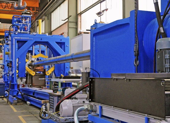
      • The Mechanical Pipe Expander machine is principally a Hydraulic Mandrel type expansion head operated by a reciprocating cylinder a controlled pressure of 400Bar for various diameters of pipe under expansion.
      • The entire mechanical equipment was supplied by M/s. MANESSMAN-DEMAG, Germany, pioneer in the field of steel pipe manufacturing.
      • The max. Capacity of pipe under expansion is 12 meter long, 60 inch dia. & 50mm thick.
      • This was the third machine of its kind & capacity in the world.
      • Our roll in the project was panel manufacturing, drawings, software development, site erection & commissioning.
  • PIPE COATING INSIDE & OUTSIDE
      • The inside & outside pipe coating line was installed basically to provide anticorrosive paint coating on steel pipe.
      • Again here also process technology was supplied by the M/S EUPEC, Germany.
      • We had supplied the entire Automation system for blaster & coating line includes AC drives Panels, PLC panels, MMI operations, Software development & commissioning.
  • TACK WELDING
    • image
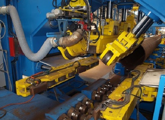
      • Tack welding, a necessary preliminary step in many welding projects, must be performed correctly to achieve optimal results from the final weld and to minimize part defects. Quality is as important in tack welding as it is in the final weld.
      • An advantage of this procedure is that if the alignment for final welding is found to be incorrect, the parts can be disassembled easily, realigned, and tack welded again
      • Tack welding is real welding, even if the welds are deposited in separate short beads. It holds the assembled components in place and establishes their mutual location, ensures their alignment, Complements the function of a fixture, or permits its removal, if necessary, Controls and contrasts movement and distortion during welding, Sets and maintains the joint gap.
      • It also Temporarily ensures the assembly's mechanical strength against its own weight if hoisted, moved, manipulated, or overturned

ICE

  • 40-TPD (TONS PER DAY) FLAKE ICE PLANT
  • 5 TPD TUBE ICE MAKER
    • image
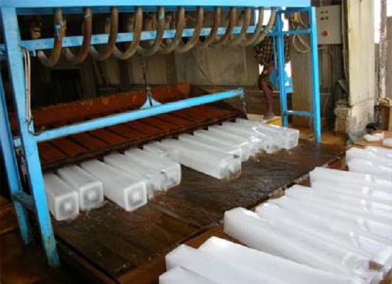
      • In This Process there are two cycles, one is freezing cycle and the other is Thawing cycle.
      • Freezing cycle: In the freezing cycle ice will be formed by using ammonia gas. Using cooling tower fan, cooling tower pump the water is supplied to the tubes for the production of ice .
      • Thawing cycle: In this cycle Because of Thawing Gas tube ice drops on the Tube ice maker Cutter then that cutter cuts that tube ice into pieces.
      • The above process operation has been done by Cabinet Systems using PLC in auto/manual operations as per system requirements.
  • RLC (RECTANGULAR LINK CONVEYOR)
      • In this process there is two cycle charging and discharging. Charging cycle: the ice formed will be stored in the ice container(capacity of ice storage will be depend on customer requirements).the ice will be levelled by using the rectangular link conveyor this operation will all the control are given both in auto/manual mode
      • In Manual Mode The Operator Can Manually Start The Motor Individualy By Start/Stop Push Button That Is Provided In The Panel And HMI
      • In Auto Mode Compressor Motor On Feedback Should Be There And After That Ice Gate Winch Should Be Down, Once The Ice Gate Winch Down Feedback Comes The Rlc Cradle Will Move Reverse Depending Upon The Time Set In The Hmi Screen After The Reverse Command Stops The Rlc Cradle Move In Forward Direction As Per Time Set In The Hmi Screen, Again When The Reverse Command Stop Lift Will Move In Up Direction As Per Time Set In The Hmi Screen.
      • The Cycle Will Repeat Once Again Until And Unless Compressor Motor Stops.
      • Discharge cycle: In this process all the ice are delivered using elevating and discharge screw conveyor. Here Ice Gate Winch Should Go Up Direction, After Getting The Up Feedback Discharge Screw Conveyor Starts And Rlc Move In Forward Direction And Lift Will Be Moving In Down Direction.

WATER TREATMENT

  • WATER – SEWAGE TREATMENT PLANT
    • image
      image

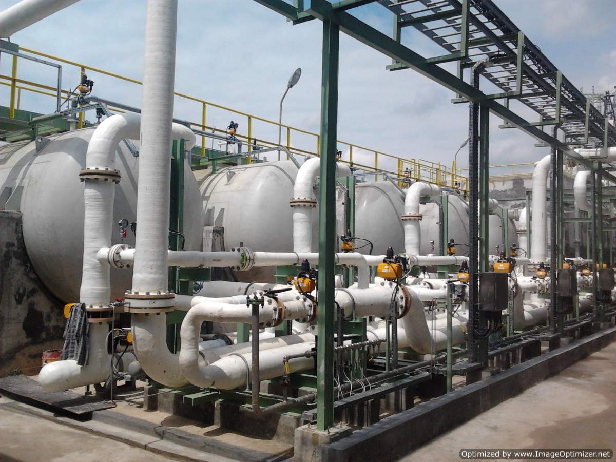
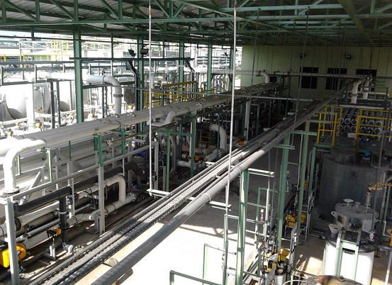
      Water treatment covers the mechanism & process used to treat water that has been contaminated by some industrial or commercial activities prior to its reuse. The control systems used here are designed for automatic operations of pumping, treatment & disposal systems. Automatic & manual operation of the Plant is possible through PLC.

      CLIENTS:
      M/s. Thermax Limited, Pune
      M/s Metito, Indonesia
FURNACE

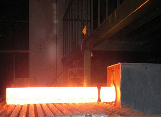
  • Roler Hearth furnacel
  • 100 TPH PUSHER TYPE BILLET FURNACE
    • image
      image
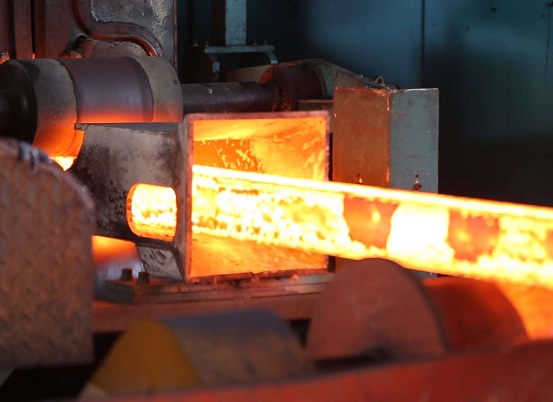
      • This type of furnace is used Clear the surface of billets by making it Red Hot. Typically there are 4 furnaces (2 Heating Zone, 2 Soaking zone). Billets are pushed inside furnaces through Pushers. Now once billets are inside the furnace, Cabinet Systems through its automation does the further process.
      • The temperature inside the furnace is controlled by the 2 thermocouples (Control temperature & Safety temperature) which in addition is controlled by PID controllers. For firing the burners in the furnace a mixture of air (combustion blower) and gas is used.
      • UV feedback from Pilot burners used in Soaking Zones are taken for Main burner start. These processes are then followed by the PID processes for controlling the temperature of air and gas ratio.
  • BLAST FURNACE GAS FLARE SYSTEM
    • image

      BF gases flared in the Flare stack of various chemical processes cannot be vented directly into the atmosphere, hence they are deliberately burnt. The burning of gas should be complete so that it reduces pollution & helps to maintain cleaner atmosphere. For flare system to function properly, the flow under emergency conditions must be evaluated.
OEM

image
image

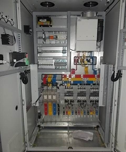
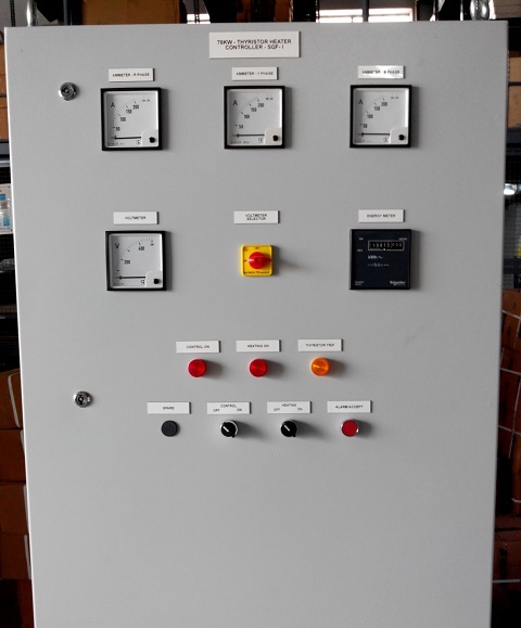
Cabinet has been providing exceptional OEM services to Industry leaders and some emerging companies since the past several years. On time performance and quality has been our major motto which has also benefited our clients immensely.

Some of the major Cabinet’s OEM are as follows:
  • Honeywell: HTS division for DCS , marshalling and PDB panel
  • Demag Cranes & Components Ltd.: Standard crane panel
  • Liebherr India Ltd: Tower crane panels, cabel looms
  • Bekaert : Wiredrawn machine panelling
  • Advance Energy: Thyristor panel
  • IMA: Packaging Machinery